Green dining
THE DEVELOPMENT OF A STORAGE COOKER THAT COULD BECOME THE HEART OF YOUR HOME
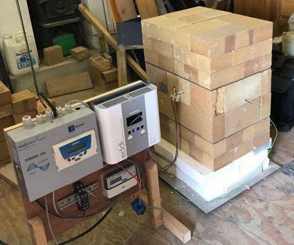
The storage cooker is inching closer to the final product - the image above is of Version 03 in the workshop. This will ultimately be a demonstration model that will be installed in to a family home for further testing and monitoring and we plan to share every stage of this process in this blog. The thermal store is up and running without insulation and the temperature of all surfaces is being measured to determine how the stored energy is being distributed.
The image above is of the first two layers of high temperature fire bricks of Version 03, supported on three layers of 50mm thick high temperature ceramic insulating boards. There will be a stainless steel plate used to hold the bricks in place, to conduct heat to a Plate Heat Exchange (PX) unit and to provide fixings for the Pyrogel insulation. You can see a tiny green cable running from underneath the unit - this is connected to a thermocouple on the floor under the unit to measure the temperature of the floor throughout trials.
How does the cooking happen?
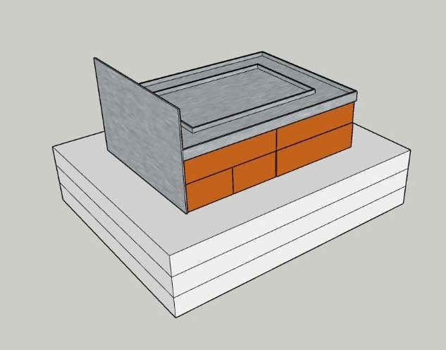
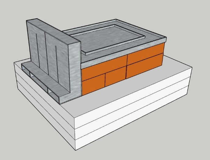
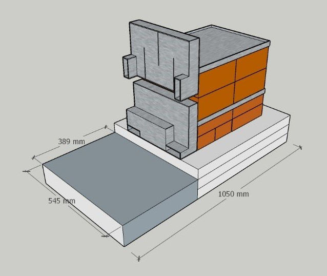
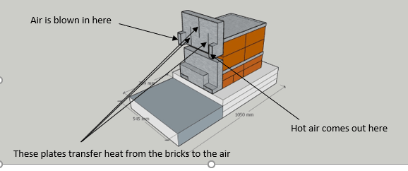
The diagrams above show the next stage of the project - attaching the stainless steel plate (on the left) and then attaching the Plate Heat Exchange units (as seen on the right). Two Plate Heat Exchange units will transfer the heat from the brick core to air that is used to a) heat the main ovens, like a fan oven, or b) heat air that will be used for heating space in the house. These boxes will have three openings side by side at the bottom of the box - one at the back, one in the middle and one at the front. Because the openings are at the bottom, there won't be any natural convection currents (hot air rising) driving the air in and out. This means that there won't be any uncontrolled air movement and thus, any uncontrolled heat transfer or heat loss.
We will be using a fan from a fan oven to draw air out of the middle opening when heat is needed in the oven. The plates inside the box result in the very hot air at the top of the box being drawn out first (giving instant heat) and the coolest air at the bottom of the oven being drawn into the openings at the back and front to replace the air that has been drawn out. The fan will be speed controlled which will give very precise instant control over the rate of heat transfer and this the temperature in the oven. There will be two of these units - one at the bottom of the unit (as shown above) and another at the top. The top unit will be for the hot oven and the bottom for a cool oven or heating space - a little like the different ovens in a traditional range cooker. There will also be one or two hot plates on top of the unit for frying/boiling.
The above image shows the cooker with the two Plate Heat Exchange units (one on top of the other) for the two ovens and the rough dimensions of the overall unit. The below image describes the flow of air and heat
